I got inspired by reading an excellent GEO-Quarterly article describing Jean-Luc Milette’s pioneering work on X band weather satellite reception.
Then came across Alan’s @Aaang254 extraordinary for every satellite enthusiast SatDump software !
There is nothing more to be said , just take a look at Github and sutdump.org!
For the direct reception of weather / earth observation satellites on 8 GHz to have some margin typically a ~1.2 m or bigger dish is needed, a AZ/EL or even better a X/Y rotor, a suitable feed and low noise amplifier, a downconverter and an SDR with the appropriate software. Depending on satellite even a smaller dish maybe good enough (see Scott Tilley’s 66cm prime focus dish )!
There are not many SDRs around supporting the high sampling rates required by X band satellite downlinks . To mention some there is LimeSDR – USB , Blade RF 2.0 and the more expensive USRPs . Real-time processing (demodulation/decoding etc) isn’t possible at these high rates (e.g over 20 MSPS) even with a powerful PC so the whole pass needs to be recorded and post-processed offline.
Below are some X band LEO weather/earth observation satellite frequencies:
| Satellite | Freq (MHz) |
| NOAA20 | 7812 |
| NOAA21 | 7812 |
| SUOMMI NPP | 7812 |
| FY3D | 7820 |
| FY3E | 7860 |
| FY3G | 7790 |
| AQUA | 8160 |
| AURA | 8160 |
| TERRA | 8212.5 |
There are also Elektro L2 / L3 geostationary satellites at 7500 MHz.
More frequencies following the links below:
ANTENNA / TRACKING
I was lucky enough to find a 1.4 m prime focus dish with f/D 0.38 (Andersen True Focus) . It is not easy to find prime focus dishes nowadays…
For tracking I use an SPID BIG RAS AZ/EL rotor and the Rot2Prog controller . The version of my Rot2Prog controller had relays to switch polarity/power and these got damaged once a week (!!!) after tracking a few passes. After replacing those a few times, the relays were successfully replaced by BTS7960 H bridges following Gerhard Schweizer’s modification, see here:
I use my own software , Satellite FUN, which calculates passes/tracks satellites, programs the local oscillator and starts recording/decoding. So the whole procedure has been automated now.
You can find more info clicking on this text.
When a small dish is used, there is not much margin in the link budget so besides antenna G/T etc accurate tracking is also very important. I initially used HamLib but position update intervals seemed to be limited to about 1.5s so decided to switch to directly writing to the controller serial port and updating position down to every 0.5s or when the satellite has moved more than half a degree. Need to mention though, that even with HamLib results can also be excellent.
After some feed optimizations , I am now getting good results with all satellites in the table above.
NOAA and Suomi NPP have lower signal and lots of fading due to some issues with their antennas.
RECORDING A PASS
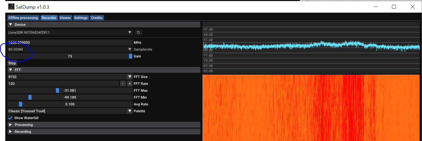
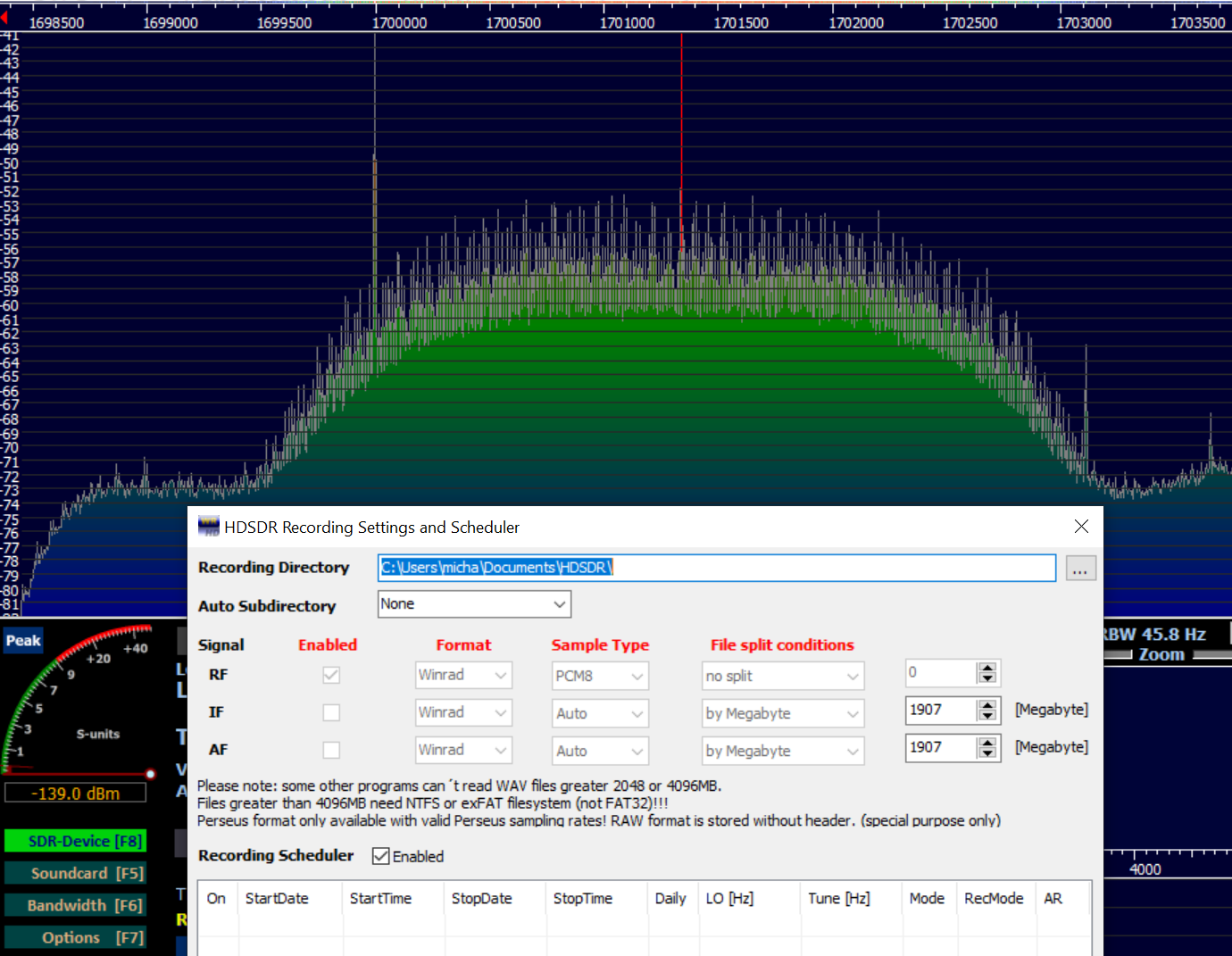
Recording is done with HDSDR or SatDump.
For HDSDR Jean – Luc’s special dll for the LimeSDR supports rates up to 60 MSPS. Proper HDSDR settings are RF/Winrad/PCM8/No split.
Recording can also be done with SatDump allowing rates up to 80 MSPS.
For daily lengthy recordings at these rates it’s best to use a dedicated SSD given the total written bytes limitation. I use a 1 TB Western Digital SN850X SSD just for recordings , isolated from the OS. In case it breaks , the OS will not be impacted.
HDSDR : Check for dropped samples under misc/misc options/show status:

DEMODULATION / DECODING SOFTWARE
The resulting baseband file is further postprocessed in SatDump or Jean-Luc’s demodulator/decoders.

8 GHz LNA
I designed my own LNA . The very first prototype consisted of 2 stages with some spare MGF4919Gs . PCB was made etching the board at home in a FeCl3 bath and using thin wires for VIAs. Without any tuning noise figure measured was less than 1 dB.
The second version uses a couple of CE3512K2 devices . This was again etched at home but this time for VIAs I used LPKF proConduct paste with very good results.
Measured noise figure of the second version is around 0.8 dB and this is about the target noise figure of the first stage.
Other commercially available LNAs would be e.g Kuhne’s 8000B or surplus items found on ebay (like MITEQ-AFS3-08500960-15-10P-TC-4) etc.


DOWNCONVERTER
The LNA is followed by a VBF-8000+ Mini-Circuits 8 GHz band pass filter which is connected to a 20 dB gain block. Then comes the ZX05-153-S+ Mini-Circuits mixer . I use Kuhne’s programmable MKU LO 54 to 13600 PLL Oscillator. Frequency can be altered over the serial port in 1 Hz steps and it accepts a 10 MHz external reference.
In the future, as time permits, all these may be replaced by a single PCB featuring the LNA, mixer, filters , PLL etc.
FEED EXPERIMENTS AND SUN NOISE
On X band to get started one could use just an open waveguide or a helix with a few turns . See Kunrad Unger’s tweet here.
I wanted to design my own feed using 3D EDA. For best wideband performance I ended up using Chaparral choke.
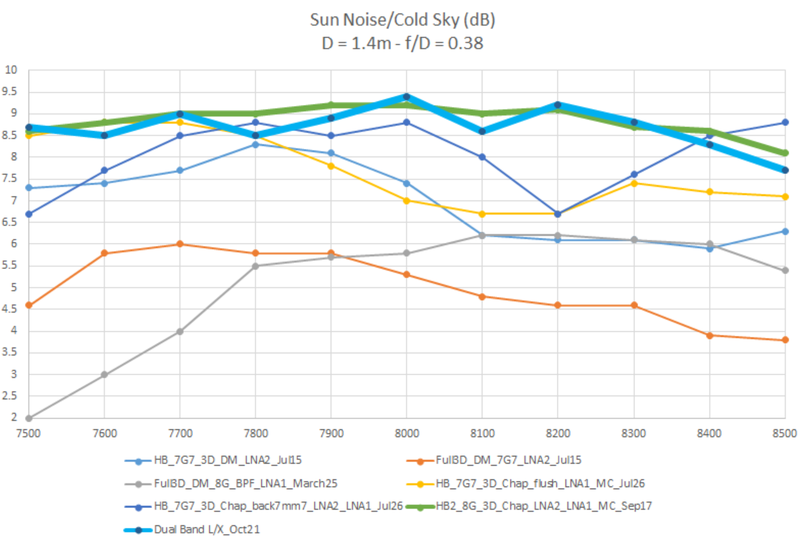
With the 1.4 m dish , the 0.8 dB NF LNA (see measurement above) and my latest version of a hybrid Chaparral feed , I am getting about 8.5-9.3 dB sun noise over cold sky ( SFU ~210 at 8 GHz) .
Some notes about measuring sun noise can be found here
Plot below shows the sun noise / cold sky for different feed/LNA configurations with the green trace being the best so far currently in use.
The hybrid feed consists of a copper pipe with a septum polarizer inside and a 3D printed / copper plated Chaparral choke. Dimensions have been optimized in 3D EDA for best G/T, circularity etc

Approximate radiation pattern using the sun as a signal source just taking noise power measurements at a few points around the maximum :

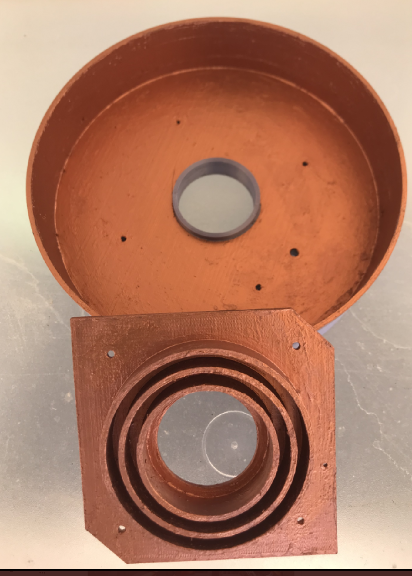
I have been experimenting with different feed types. All use a septum insert to create LHCP/RHCP polarization. The first version was fully 3D printed and then copper plated in a bath and is described below.
Later the waveguide /septum part was replaced by copper to reduce losses and the dual mode section was replaced by a 3D printed/plated Chaparral choke.
This gave best results as sidelobes in the Chaparral case are 25 dB down in the entire frequency range of interest (7.5-8.5). The dual mode gives lower sidelobes (35ish) but this is only true around the design frequency.
For wideband applications the Chaparral seems to be a better compromise.
Dimensions of my X band RHCP/LHCP Chaparral feed can be found below. It is the result of design, simulation and optimization work in 3D software.
STL files for the Chaparral, the septum polarizer and a copper pipe cutting guide have been uploaded to Thingiverse .
Please note that only the Chaparral section is printed and plated. The waveguide (pipe ID=31mm) and septum are made of copper. The provided waveguide and septum STL files are only cutting guides and are not to be plated.
Figure below shows the dimensions of my X band feed.
For optimum results, it is absolutely important to use a pipe with inner diameter of 31mm. Scaling the septum to make it fit in whatever pipe diameter available will not work.
The feed can be scaled to move it to other frequencies but then including pipe dimensions !

After successfully developing this single X band feed, I decided to add a patch for L band. This would allow having a single feed in the focus for both bands. Based on the single band dimensions , the whole feed was re-simulated and dimensions adjusted accordingly.

X band performance was not significantly affected as can be seen on the plot below where sun noise over cold sky data for the dual band case has been added.
The green thick trace on top is for the single X band feed. The blue thick trace is for the dual band case.
As mentioned above, the waveguide/ septum section is made of copper .
The patch ground base, the patch and the Chaparral section are 3D printed (PLA) and copper plated in a bath. This is much more time- cost-energy efficient and family friendlier 🙂 to develop than machining aluminum or copper .
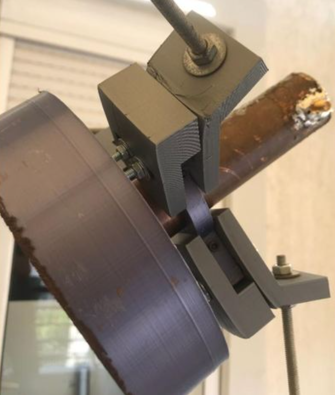
To keep the feed in the focus I designed a feed holder and printed it on my Creality CR10-S5 printer.
You can find the STL files on Thingiverse !
See pictures below.
SOME ISSUES ENCOUNTERED
a) Interference
While tracking weather satellites in X band, I noticed that in some directions there is strong interference. It comes from Fixed Wireless Systems operating in the 8 GHz band according to F386-9. Signals are ~30 MHz wide and appear on fn=8000 + 29.37 +29.65*n (n=1,3,5,7)


b) Broken USB connector
Besides this strong interference that can be present in a big city like Athens , my Lime SDR had some issue with the USB connector. It would only appear as a USB2 device.
After reflowing the connector pins and ensuring a reliable attachment to the USB cable , this problem was resolved.
c) SPID antenna , wrong elevation indication
On my balcony, I hadn’t installed counterweights to my dish because of space limitations. This stressed the SPID rotor and wore out the EL ring in the low EL angles area. As a result the motor was struggling when moving up counting pulses that did not correspond to the actual movement .
I realized that in fact only a quarter of this ring is actually being used when going from 0 to 90 degrees. The rest of the ring was like new.
To overcome this problem and let it use a different part of the ring, I just removed the EL protection/limit switch under the top cover and reinitialized the controller .
Finally I installed counterweights and that reduced stress.


Below is the initial description of the fully 3D printed dual mode feed.
This is what I used at the beginning before switching to the Chaparral type of feeds.
DUAL MODE FEED FOR OPTIMUM ILLUMINATION OF A PRIME FOCUS DISH WITH F/D~=0.4
See below some pictures and details about the 3D printed / copper plated feed I currently use:
LINK TO STL FILES ON THINGIVERSE
Version 1.0 !
This is a low noise dual mode used feed for 8 GHz weather satellite reception.
Theoretically, best f/D is ~0.4 when lowest NF LNA are used, but max efficiency is at f/D~=0.6 so it might be suitable for offset dishes as well.
The 3D print consists of the base, the waveguide and the dual mode section which are connected with screws.
Two waveguide sections have been included: one for linear polarization and another one for both RHCP and LHCP polarizations on separate SMA connectors.
This work has been based on the W2IMU/N2UO 23cm design found here:
http://ok1dfc.com/EME/technic/septum/N2UO%20opt.pdf.
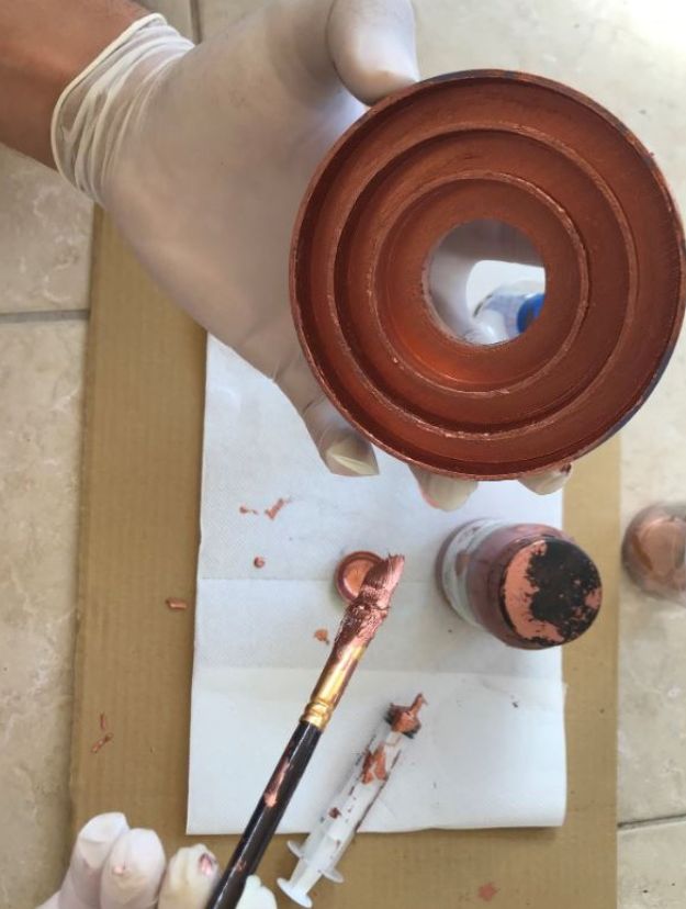
After printing, it has to be painted with a conductive paint and then electroplated in a bath.
It is absolutely important the resulting surface to be as smooth as possible.
Roughness will result in losses so patience when sanding/smoothing will pay off !
I used PLA and smoothed it with sandpaper starting from grit 500 up to 2000.
Conductive paint and plating solution used were bought from https://www.tifoo.de/
Painting has to be carefully done paying attention not to leave any blank areas.
If ABS/ASA are used I guess the smoothing process can be expedited in acetone vapors or the like.
The final efficiency of the feed depends on surface roughness and the presence of any non-plated gaps.
Plating current should be like 50mA/cm2 so for a 100cm2 piece , plating voltage should be gradually adjusted until 5A total current is reached.
Notes:
1) You could try scaling it in the slicer to make e.g a feed for 10 GHz!
2) For 8 GHz SMA probe length inside the waveguide is 7mm .
The dimensions of the block where the SMA sits had been adapted so that no tuning is necessary when these connectors from Kuhne are used or the equivalent Amphenol 132147 e.g from Mouser leaving just 7 mm inside the waveguide. These connectors are about 17.8mm long and the Teflon section is about 15mm.
3) The Teflon section in the waveguide needs to be cutoff.
4) The Teflon section in the SMA block can be painted and plated to avoid having to rely on the plating inside the hole.
5) The SMA connector itself can even be soldered onto the plated feed !!!
Obviously, it is not as robust as on a feed of metal but should be good enough for fixing it once with an SMA torque wrench. Don’t push it too much though 🙂
6) In the 7.75-8.25 range simulated sidelobes are lower than 25 dB, simulated axial ratio less than 3dB in the entire 100 degrees radiation angle and measured isolation better than 25dB.
If you build one, please let me know how it goes !
73 de SV1CAL Michael