There are … ambitious future plans ( 🙂 ) to build a large 6m parabolic dish antenna for 23cm Moonbounce (EME – Earth Moon Earth Communication)
By simulating the whole setup in CST , the goal was to find out which is the optimum f/D for maximum G/T over a wide elevation range , assuming a dual mode low noise feed is in the focus .
This simulation project was inspired by RA3AQ’s excellent presentation .
The title of his work : Efficient dish feeds to get a best system noise performance – Presentation for Orebro EME meeting 2013.
As mentioned , a dual mode W2IMU/N2UO horn will be in the focus .This feed is known to have a clean radiation pattern with low side and back lobes. The feed alone has been simulated and the radiation pattern has been imported into OM6AA’s excellent Antenna Noise Temperature Calculator with shows total “gathered” noise and G/T over elevation angle. This dual mode horn seems to be collecting about 5 Kelvin noise at 90 degrees elevation angle (cold sky)
After simulating the dual mode feed stand-alone, a parabolic reflector of 6m diameter has been added to the simulation bench. The following f/D ratios have been simulated : 0.2 up to 0.6, step 0.05.
The goal was to find the optimum f/D ( thus define the paraboloid to be constructed) which will result in best receive capabilities without sacrificing too much transmit gain.

For each f/D above, the radiation pattern file was then imported into the Antenna Noise Temperature calculator software.
This software calculates antenna noise (Tant) and G/Tant vs elevation angle.
It seems that the optimum f/D is around 0.4 and this is what I will build in the -not too distant- future I hope 🙂
Let’s see the details:
Besides the noise collected by the antenna due to sky noise, spillover and side/back lobes , System G/T is also affected by LNA noise and the noise added due to the limited TX/RX separation between the 2 ports of the dual mode feed (LHCP/RCHP)
For best reception G/Tsys must be maximized.
G is antenna Gain , while Tsys=Tant + Tlna + Tiso
The nominator is the antenna gain. The denominator is the total noise entering the receiver.
The gain which is defined by the geometry of the dish (f/D) and the radiation pattern of the feed. Since we have selected the dual mode feed, in our case f/D defines the gain. The plot below shows gain over f/D with the dual mode feed in the focus (vertical axis : Gain in dB, horizontal axis f/D , D=6m) 
But the denominator is also as important for best reception.
The plots below show System G/T for the following LNA noise figures : 0.15, 0.2 and 0.25 dB which are realistic numbers for optimized 23 cm EME setups.
The first 3 plots assume that TX/RX isolation is infinite (not the case in reality) while the last 3 plots take the simulated limited TX/RX isolation into account
Below LNA NF =0.15 dB , TX/RX isolation assumed infinite (Tiso=0 K)

Max G/T about 24 dB for f/D =0.35
Below LNA NF =0.2 dB , TX/RX isolation assumed infinite (Tiso=0 K)
Max G/T about 23 dB for f/D 0.3, 0.35 and 0.4
Below LNA NF =0.25 dB , TX/RX isolation assumed infinite (Tiso=0 K)

Max G/T about 22.5 for f/D 0.4
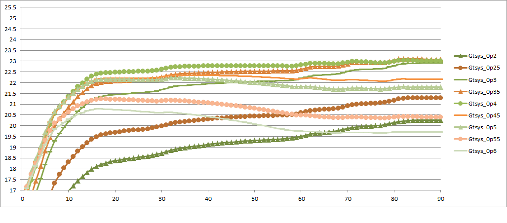
Now in reality TX/RX isolation limits G/T . See below its impact for LNA NF of 0.15, 0.2 and 0.25 dB
Below LNA NF =0.15 dB , TX/RX taken into account–>Tiso>0
Max G/T about 23 dB at 90 degrees elevation . G/T about 22-23 dB for elevation angles over 10 degrees
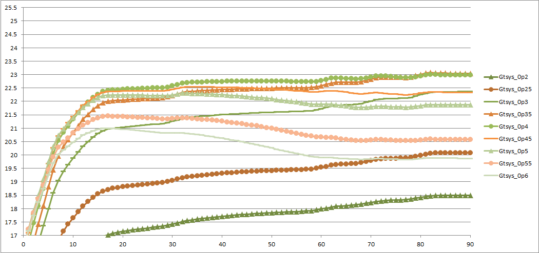
Below LNA NF =0.2 dB , TX/RX taken into account–>Tiso>0

Max G/T about 22.5 dB at 90 degrees elevation
Below LNA NF =0.25 dB , TX/RX taken into account–>Tiso>0

Max G/T about 22 dB at 90 degrees elevation
Please keep in mind that the accuracy of the simulation results have not been confirmed. Especially regarding the simulated isolation between TX/RX ports. Getting accurate simulation results (especially s-param) requires huge amounts of RAM and CPU power, accurate meshing etc.
Low f/D means that the feed is closer to the large reflective area of the dish resulting in worse isolation. On the other hand larger f/D give better isolation between TX/RX ports.

From the results above it looks like an f/D close to 0.4 is a very good compromise between RX and TX . TX gain will only be about 0.6 dB lower compared to max gain which happens when f/D =0.6
Regarding RX capabilities , looking at the plots above, for elevation angles over 10 degrees the green line (f/D =0.4, D=6m) seems to result in best G/T up to 90 degrees elevation for LNAs with NF around 0.2 dB. An LNA of 0.15 dB at 1296 MHz , a dual mode dual polarization feed and a 6m dish could result in G/T 22-23 dB for elevation angles over 10 degrees.
Note1: The effect of the support structure (typically 3 or 4 legs holding the bulky feed in the focus) has not been taken into account in this simulation work.
Note2: Inserting a metal disk of certain diameter in the dual mode section of the feed (RW3BP’s suggestion) can significantly improve TX/RX isolation. The effect on radiation pattern is minimal. Simulation shows some indications that the metal disk may increase a few Kelvin the Tant temperature though which means that it may only be beneficial when native TX/RX isolation is less than about 20 dB. For example, in the case of my 2.5 m dish (f/D=0.4) isolation was only 13 dB which could easily be increased over 30 dB with the use of a metal disk. See details here
Best 73s,
Michael Margaras – SV1CAL
