EME FUN antenna controller gets Azimuth and Elevation commands from my EME FUN software (see related article) and rotates the antenna/dish by switching AZ/EL rotor/actuator supply polarity and counting pulses while in motion. Motion speed can be adjusted independently for Azimuth and Elevation. The controller could be used with all AZ/EL antenna setups that use rotors or SAT-TV actuators sending a given number or pulses per degree.
The design is based on a PIC16F877A micro-controller, communication with EME FUN software is done over RS232, it features UP/DOWN/LEFT/RIGHT buttons for manual control and an LCD display to show pulses and position in degrees. In manual mode, the user can select between slow or fast motion speed by setting a switch. In automatic tracking mode, at motion start or when approaching the target Azimuth or Elevation , the antenna slows down. When the antenna position is far from target AZ/EL , motion speed is switched back to fast mode. Slow and fast motion speed, thresholds and pulses per degree can be set within EME FUN software independently for Azimuth and Elevation.
If required, PWM speed control can be disabled . This requires 2 more DPDT relays to be installed (totally 4 on board).
In PWM configuration, on the board there is an external I2C EEPROM , 2 DPDT relays, 2 PWM generators , 4 Power-Mosfet switches and a couple of I2C DACs. In the future, control over Ethernet will be added.
The basic components are listed below:
PIC16F877A, LM2575HV, MCP4725, SG3525, 74HC1G32 , 78M05 , 16×2 LCD , IR2110, MAX232 etc
Except for the 16F877A MCU all other ICs are SMDs.
Code for the PIC has been written in C using SourceBoost and the QL200 development board.
The board main supply must be in the following range : 12V up to 60V.
If needed, each Azimuth and Elevation rotor/actuator can get its own independent supply which could be much higher than the 60V limit for the main board.
TVS diodes protect the circuit and the rotor windings from huge spikes .
The schematic diagram can be found here: (Updated Jan 27th,2017)
The first version of the PCB has been in action a while now in SV1DNU’s setup. He uses 2 satellite TV actuators for AZ/EL and wanted to add moon tracking option.
The board has also been tested with the BIG RAS AZ/EL rotator in my setup and with an old small satellite TV rotator made by IRTE.
BIG RAS uses reed switches and sends 2 pulses per degree while the old IRTE rotator uses a hall effect sensor and sends about 120 pulses per degree in EL and about 60 in AZ direction per degree.
In this second version of the board I decided to experiment with independent AZ/EL PWM speed control ,added some switching regs for efficiency ,made the PCB smaller etc.
UPDATE May2018:
Schematic/Layout/PIC source and hex files uploaded to Dropbox:
DesignSpark 6.0 files and PIC16F877A source/hex files
Important Notes:
Not all schematic pages are implemented on the layout (e.g IR2110 stuff ).
DesignSpark 6.0 was used .This is not the latest version but seems to open with version 8.1 (May2018) as well with no issues.
PIC source code written in SourceBoost IDE (BoostC).
Use at your own risk! 🙂
Don’t consider this as a final project. Use it for your experimentation and fun!
In the future I will probably redesign it using a newer processor with more memory and features…
FYI, some PCB manufacturers , such as PCB POOL were the prototypes were built, accept DesignSpark .pcb files.
Below is a screen shot of the layout (4 layers) done in DesignSpark 6.0 :

Below boards assembled , up and running 🙂

Actually only 2 DPDT relays are required.

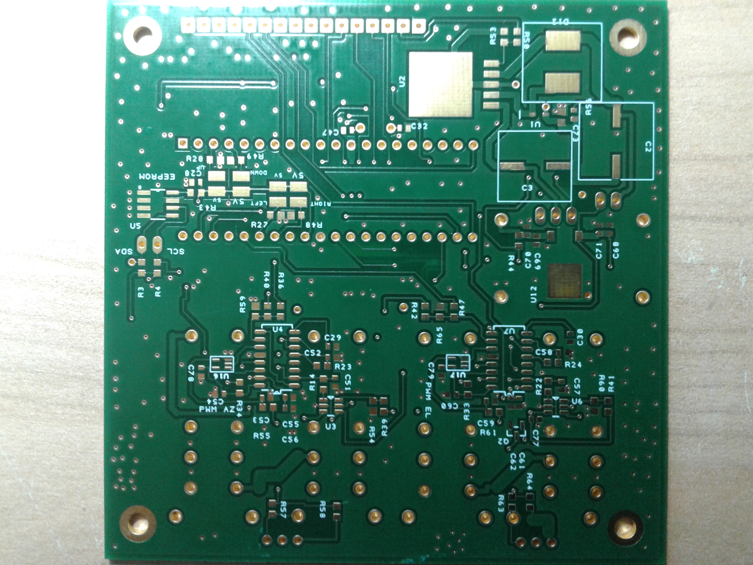
Blank board top layer

Blank board bottom layer
Edited by Michael Margaras , SV1CAL

Hi Michael. I was looking for this kind of controller for my own 12 foot mesh dish, Having de linear actuators y could not find up today a serious design.
Could you help to me?
I am not an engineer but have a lot of experience in Rf and microwaves.
Yours
Fernando
LU1HKO. Active en EME 144 mhz from FF78vn. since 2012
Hi Fernando,
Thanks for your message. I designed this controller 2-3 years ago and use it mainly with a small modified IRTE AZ/EL rotator to capture signals from weather satellites. Based on latest debugging findings I need to update the schematic diagram and then will post it on this page so that you can take a look. If I find some time I will also update the PCB.
So please check back again.
Honestly, I don’t plan on selling any controllers as I really don’t have the time to support such an activity 🙂
Best 73s,
Michael SV1CAL
Hi Michael.
Thanks for your reply.
I am near my retirement from work life and I will have too much time to enjoy ham radio. I wish you could do the update and enjoy also investigating and experimenting . I also will.not like to do bussines with this. only have fun !!.
Thanks again for your time.
FernandoCostarelli LU1HKO
Enviado desde mi dispositivo Samsung
Quick update : The schematic diagram can be found here:
https://www.dropbox.com/s/9rs6ja0e06upbjf/EME_FUN_CONTROLLER_1v1_SV1CAL.pdf?dl=0
Hi Michael,
Compliments on a very informative and interesting Page and project.
If I may as . are the PCBs Boards available please?
regards and 73’s
Mans. 9H1GB
Hi Mans,
Thanks for your message!
I don’t have any spare PCBs, sorry for that.
Probably will fabricate a new board with updates later this year but this depends on free time and other projects 🙂
Regards,
Michael ,SV1CAL
Hi MIchel.
Now just retired, I will be testing the project. Also I will need a single Board, Here is difficult to get a decent builder for a decent board.
If possible, let me know if you plan to supply some boards.
Thanks again and have fun.
LU1HKo
Fernando
Hi Fernando,
I am sorry to say that I have no spare boards anymore. Will need to find some time later this year to produce a new board based on the published schematic.
All the best 73s,
Michael
OK, Michael.
I my dish will be here all the time !!! Hi Hi !!
Gl anf 73
Fernando
LU1HKO
IF you could send the layers I will find a local provider to print the board. May be?
Yours
Fernando. LU1HKO
Hi Fernando, I haven’t found time to work on this project. But I will post my Designspark files and source code for the PIC later this week. Please be aware that this is a experimental hobby project I did some years ago, just for fun and to learn new things. It is not a final product. This means that most probably you will have to edit the code and do changes on the boards to make it work on your setup. Regards, Michael
Hi mIchael, Thanks for reply. I am a Ham and I love to experiment, surely may be problems but it will be a pleasure to help in the final version of this great project. I will be here or at fcostarelli@msn.com .
Have a nice weekend!
Fernando LU1HKO
Now I am preparing to receive the 2 new China lunar orbital satellites at 435 Mhz and more than 20 dB are needed the 4,5 mts dish will be very useful.
Hi Fernando ,
Please check your msn mail .
73s
Michael
Schematic/Layout/PIC source and hex files uploded to Dropbox:
https://www.dropbox.com/s/y505hoo89wrokvb/EME_FUN_controllerUpload.zip?dl=0
Important Notes:
Not all schematic pages are implemented on the layout.
DesignSpark 6.0 was used . This is not the latest version but seems to open with version 8.1 as well with no issues.
PIC source code written in SourceBoost IDE (BoostC).
Use at your own risk! 🙂
Don’t consider this as a final project. Use it for your experimentation and fun!
In the future I will probably redesign it using a newer processor with more memory and features…
Best 73s,
Michael SV1CAL