March 2025
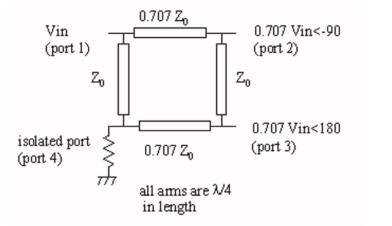
Typically weather / earth observation satellites use right hand circular polarization (RHCP) in their downlinks in L and S band. At the receiving station, a helical or patch with LHCP polarization in the focus of a parabolic reflector is mostly employed. To obtain circular polarization one could also use two orthogonally placed probes (placed 90 degrees to each other ,V/H) in a waveguide and a 90 degrees phase shifter . Such a phase shifter could be a quarter wavelength coaxial line (e.g often used in turnstile antennas ) or a 90 degrees hybrid that ensures that the probes get excited by equal amplitude (-3dB) and 90 degrees phase shift.
Helical antennas as dish feeds is a nice solution that is easy to construct and just works. It has drawbacks like side/back lobes and spillover reducing max G/T. In addition it’s not easy to have both polarizations in the focus of the reflector in a switchable configuration where LHCP/RHCP are peaking in the same direction.
On the other hand the use of a 90 degree hybrid and orthogonally placed probes allows for a wider selection of feed types with different radiation patterns (open waveguide, Kumar, dual mode, Chaparral etc) and makes toggling between RHCP/LHCP easy by either selecting port 1 or port 4 with an SPDT switch referring to the diagram above.
The 90 degrees shift could also be done in the digital domain. I used my LimeSDR-USB receiver which has 2 synchronized RX chains (2X2). Channel A gets signal from the vertical probe and Channel B from the horizontal probe.
A simple feed has been designed in CST Learning Edition with the 2 probes orthogonally placed to eachother . To improve isolation (e.g >25dB) the separation of the probes had to be increased .
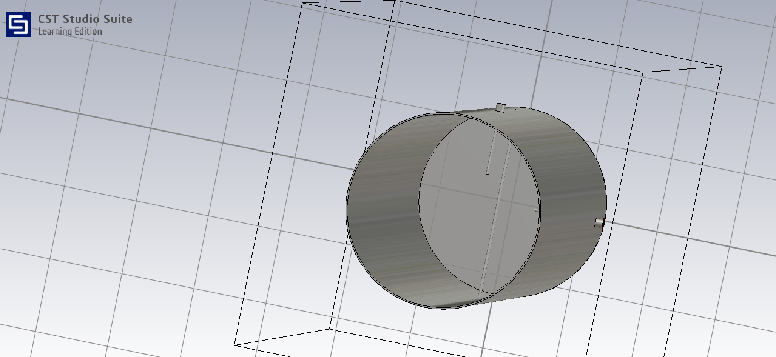
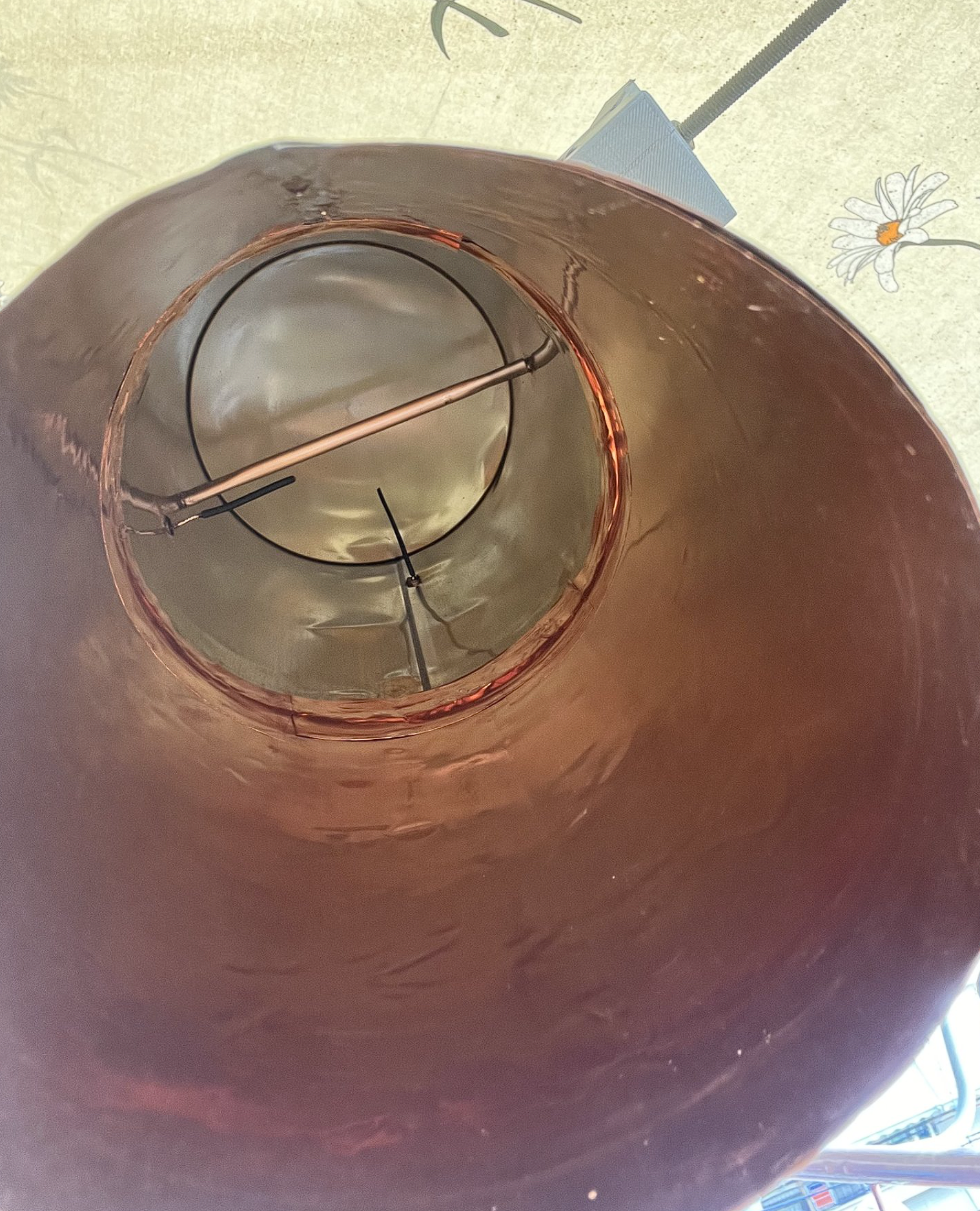
A honey can with diameter 126 mm was extended up to a total length of 350 mm. Below are dimensions from the back plate: Horizontal SMA connector 48 mm ,ground rod 73 mm and vertical SMA is 161mm . Center pin length was roughly simulated to be 42 mm but in practice started with a longer piece and cut to length tuning with a VNA.
The rod in the picture serves as ground for the probe .This simple technique is found in almost all TV LNBs.
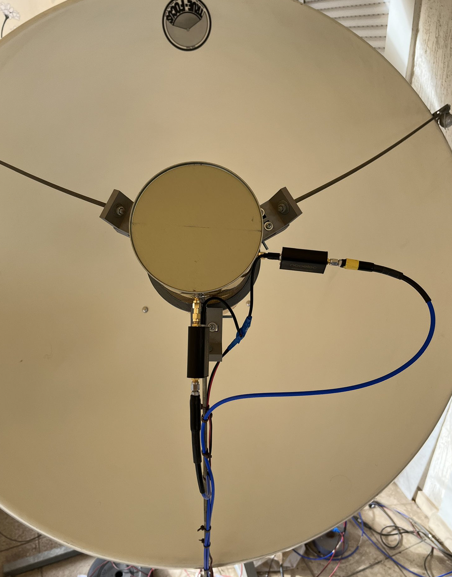
Identical Noeelec SAWbird LNAs (NF ~ 1.5 dB due to band pass filter) are behind each port and phase matched Mini Circuits blue cables ensure that the paths from the feed to the LimeSDR are as much as possible identical. Phase matched cables are not required of course, as phase offsets are present anyway e.g in the feed itself, the 2 LNAs, the A/B Lime paths not being identical etc. Regarding the LNAs, I measured them with a VNA and as expected they are pretty well matched with gain imbalance being around 0.2 dB and phase imbalance of less than 10-15 degrees at 1700 MHz. In any case the impact of those phase imbalances can be canceled out in digital.
The picture below shows the feed , the 2 LNAs and cabling going to Lime’s Channels A and B.
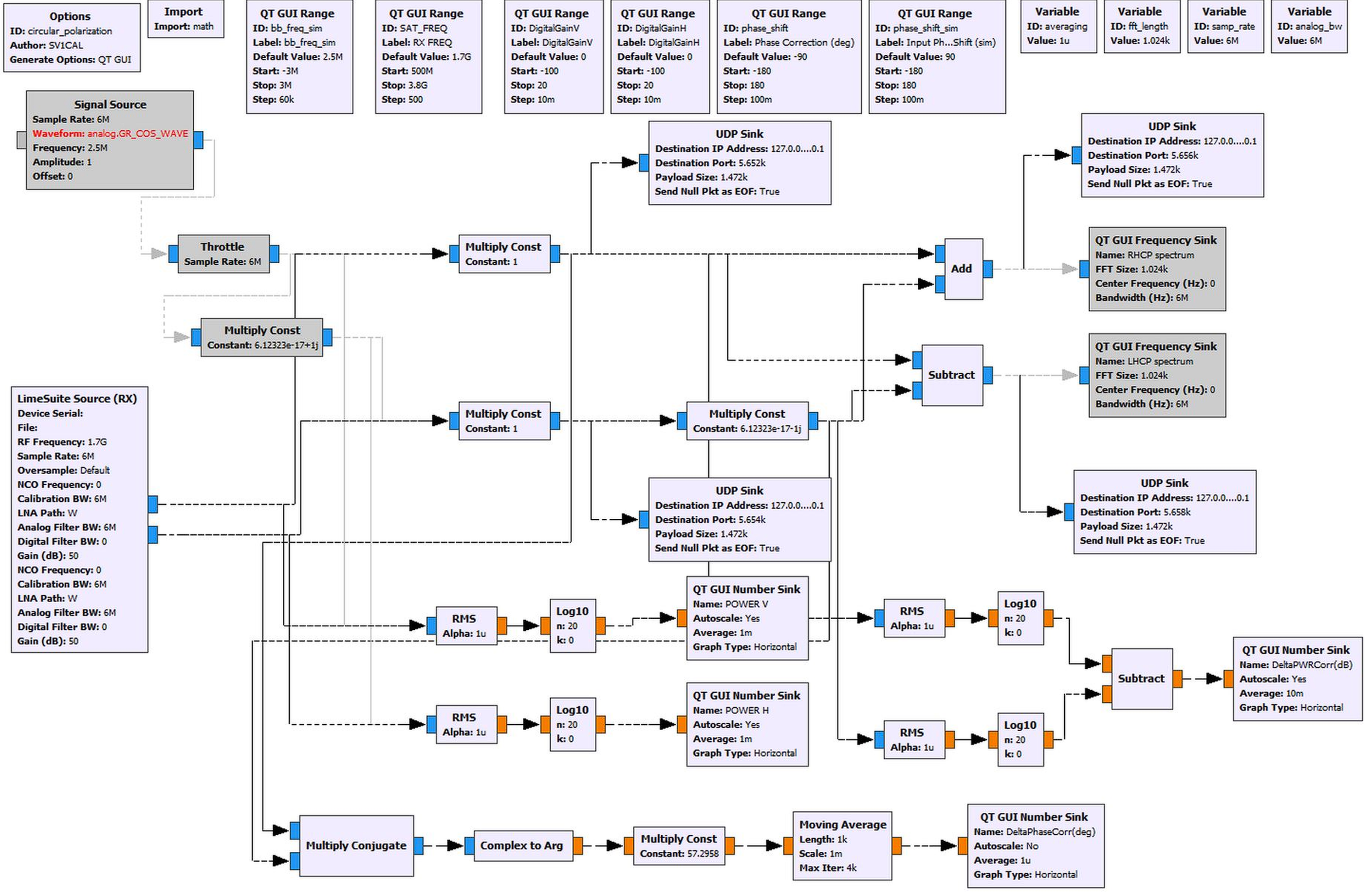
Below is the flowgraph used in Gnuradio 3.7.11 to combine the 2 linear polarizations.
The flowgraph can be downloaded from this link.
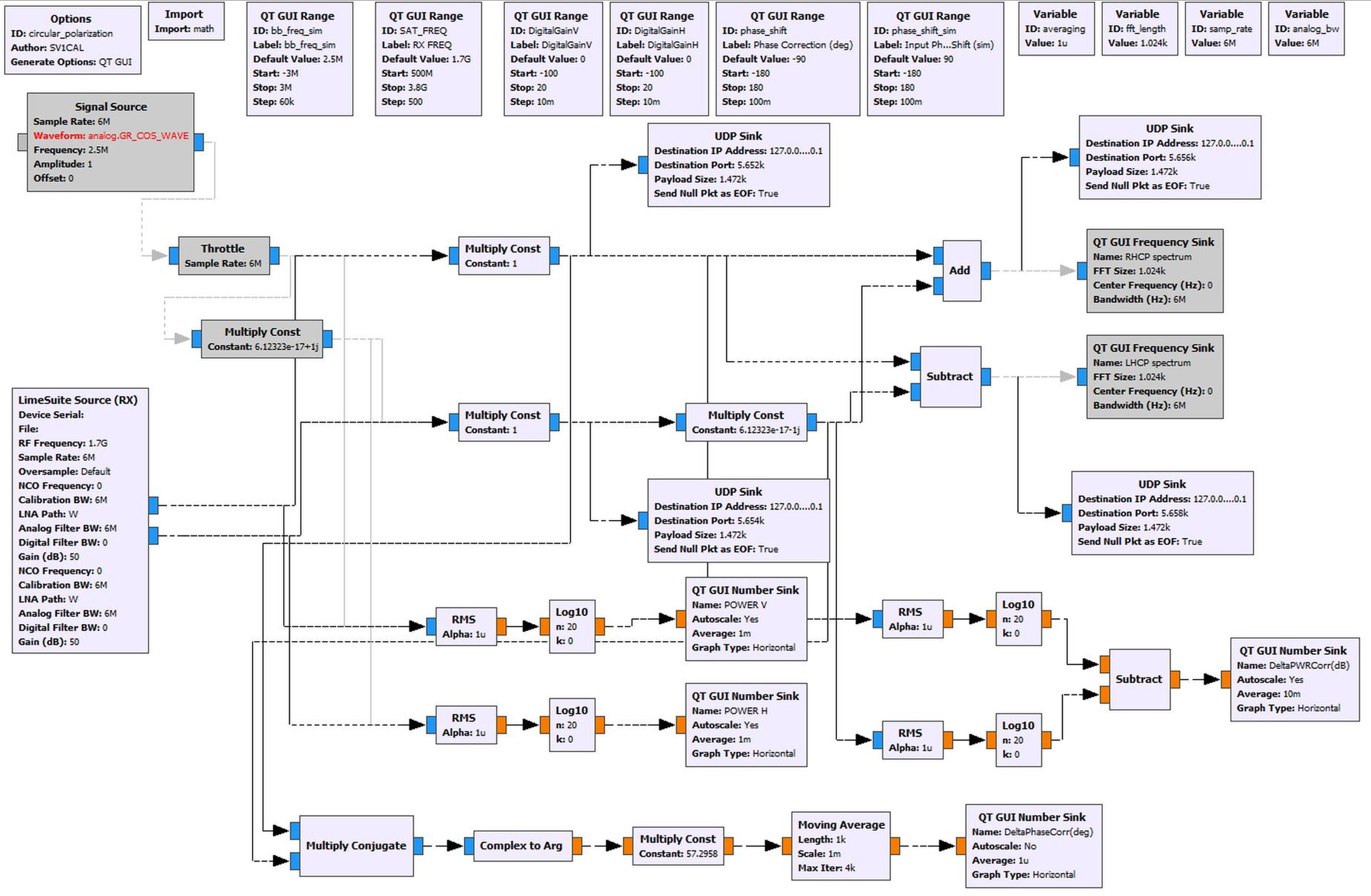
To get RHCP or LHCP channels A and B are either added or subtracted . Gain and Phase imbalance can be adjusted on the fly. The flowgraph sends over UDP 4 streams, Vertical , Horizontal, RHCP and LHCP. If the PC is powerful enough, 4 SatDump instances can process them simultaneously in real time.
As a side note , SatDump has a nice feature that it directly accepts UDP streams coming from Gnu Radio. You just have to select Network Source.
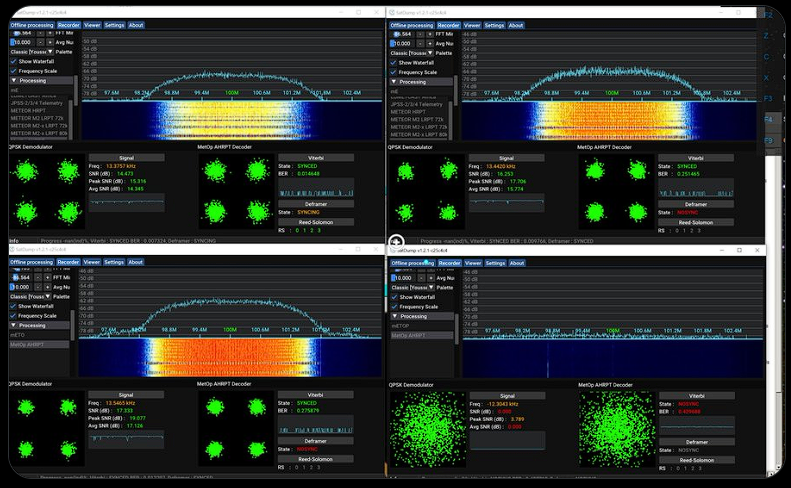
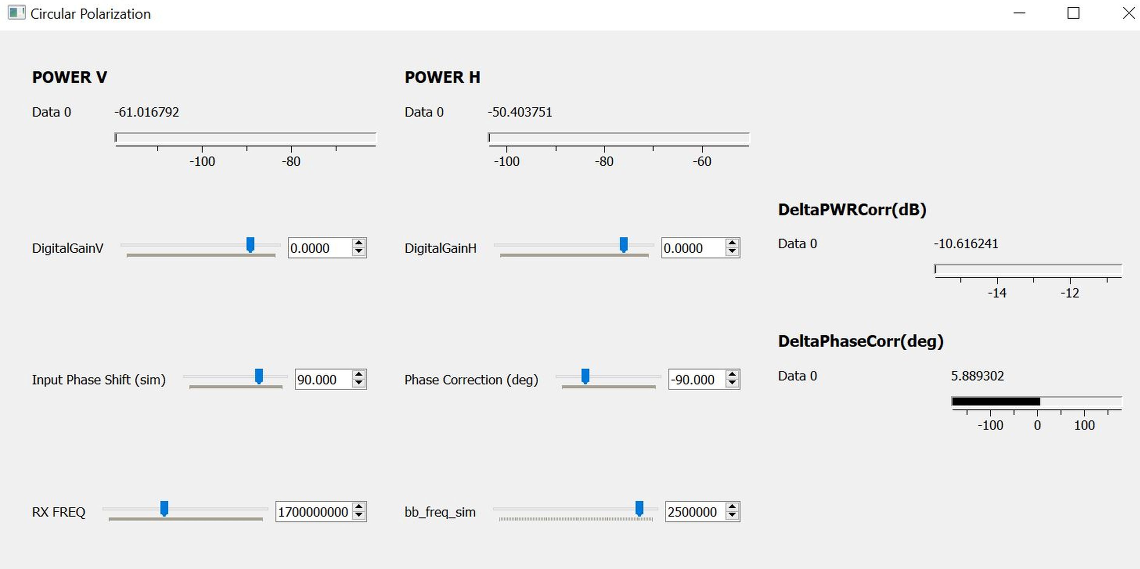
The GRC GUI in action having disabled Frequency sinks:
Below MetOp-C flies over Athens. Only phase Correction had to be adjusted to maximize SNR reading in SatDump. The benefit was around 2 dB compared to V or H SNRs.
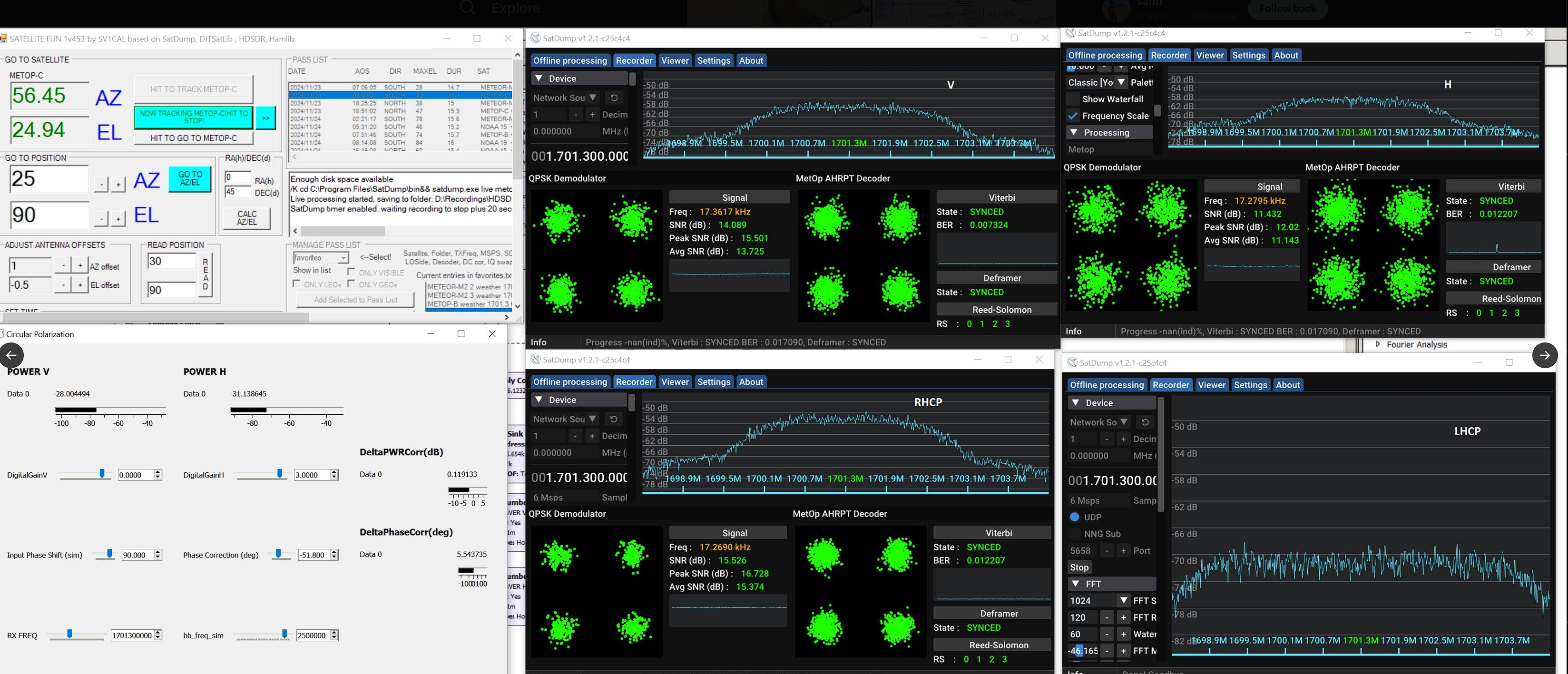
Below another NOAA-19 pass where GRC streams to 4 instances of SatDump and all are live processed. Only the phase imbalance slider had to be adjusted to maximize RHCP SNR reading in SatDump.